 This page will describe and demonstrate the process for constructing your own
marquee sign with LED lights, a parallel port, and a lot of free time. As
of this writing, I have just completed my first sign and will detail the
experience, both the successes and pitfalls, of which there were many.
This page will describe and demonstrate the process for constructing your own
marquee sign with LED lights, a parallel port, and a lot of free time. As
of this writing, I have just completed my first sign and will detail the
experience, both the successes and pitfalls, of which there were many.
Please note. More pictures, schematics and source code have not yet been included with this page. They will be included shortly.
The long road to ... somewhere
I actually first attempted this about 10 years ago. Several times in fact.
I still have partially completed circuitboards as proof. I had given up on
the project since it was going to cost quite a bit and I was having no success
with getting even a small prototype to work properly.
When I first considered building the sign, my first thought was that each
LED was a bit of memory, and that I should use actual memory (in the form
of many ICs of D-flipflops) to represent the value of each LED in the matrix,
as well as feed it power. Not only would this require an extraordinary amount
of circuitry, it would also need a lot of power. And a lot of money. And it
was entirely unnecessary. That didn't stop me from trying to build it anyway,
but I gave up quickly when I realized I simply wouldn't have enough room
on the boards I was using.
After the first failed attempt I decided to do some research and discvoered
the fact that the typical marquee sign (and most every display in existance,
including your television) relies on using just a few points of light in
a rapidly refreshing pattern that gives the illusion that all of the selected
LEDs are lit at the same time. Persistance of vision is one way of referring
to it. My first effort to accomplish this was to use 74LS273 (octal D-flipflop)
chips, each output connected to the input of the next, initially fed and clocked from the parallel port. Each bit would then control one transistor which
would allow current to flow through one column of lights. This design would
have worked, and is essentially what I'm doing now (although now I'm using
shift registers instead). However, when I tested it at high speeds, I was
getting some extreme flicker in columns that shouldn't have been lit. I
spent a lot of time experimenting with timing, but couldn't get it to go
away. After a couple of attempts to restart the project and getting the same
result, I gave up.
10 years later, I wired everything up again, and got the same result. However,
this time around, I was just a little bit smarter, and I connected the
parallel port data lines to hex inverters, through resistors. This cut down
on noise and weird signals and I was able to eliminate the flicker completely,
no matter what speed I was pulsing at.
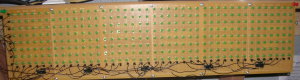
Constructing the Sign
Here is a reduced version of the schematic for the sign:
The logic is actually pretty simple. The 8 data pins of the parallel port
feed the hex inverters, each one of which controls a transistor. This
transistor either allows or disallows the 5V power to flow to the anode of
all LEDs in the row.
One of the control pins on the parallel port, (use whichever one you like),
outputs a 1 or a 0 value into the shift register as the starting value, and
the parallel strobe pin is the clock, which flips between 1 and 0 to send
a clock pulse to the shift registers. Each time the program refreshes the sign,
it will input a single 1 into the first shift register, and 0's after that.
The outputs of the shift registers each control another transistor. These
transistors each connect the cathode of a whole column of LEDs to ground.
Only one column will be lit at any one time. The 8th bit of each shift
register is connected not only to the transistor but also the input for the
next shift register in the sequence. All of the clock pins are common.
To refresh the whole display, the single 1 bit value is clocked through the
bank of shift registers, and as each column is activated, the 8 LEDs in that
column are turned on or off via the data pins (through the inverters) as
determined by the program for the current value of the pixels at that
position in the bitmap. The refresh rate can vary, but I have it set to
refresh between 150 and 200 times per second. Less than 100 per second has
noticable flicker.
There ARE some downsides to this design. The display can only be scaled so
far in this manner. Even with 40 rows, there is a significant drop in
brightness than when only 8 rows or less are being refreshed. This is because
the LED is only lit 1/40 of the time. I feed the full 5V, unresisted into each
LED for that reason. It's as bright as I can make each LED without damaging
it in the event that it stays on. A matrix with more columns (or rows) will
require a different design. Some of those potential designs will be
discussed later in the document.
Software
I have included the linux compatible software here that I'm using for
demonstration purposes. I will attempt to keep this updated over time as
I naturally update the software I'm using. The section of code where it
obtains the message from my site has been removed and replaced with a
dummy string. It's up to you to choose how you wish to feed data to the
program for display.
The functionality of the program isn't very complicated. There are three
main sets of functions. The pulse function, the ripple function, and the bitmap
functions. The pulse function simply turns the strobe pin on and off to send
a clock pulse to the shift registers. The ripple function takes the
bitmap values and the current position, and sends a 40 pixel wide stream of
data to the sign, issuing a clock pulse between each column. The bitmap
functions take a character string and convert it to a bitmap, then take that
bitmap and convert it to a grid format, where each column is represented by
a single 8 bit value (one for each LED) and matches the format which needs to
be output to the sign. This conversion process takes place only once per
message and is complete prior to any data being displayed.
Like the hardware, there are software issues as well. First to get the sign
to ripple at a sufficient speed, it's required to pulse the clock about 33000 times per second. Some of you might be aware that the linux kernel has a clock rate of between 100 and 1000 hz. What this means is, if you try to use usleep,
the kernel will block the program for a time period that's an order of magnitude
longer than we need to wait. As a temporary solution, I simply use for loops
which do nothing but count. On the computer I'm running this on, the time to
wait between each pulse is approximately 10000 cycles of a for loop. While this
works perfectly, it also makes the CPU run at 100%. That isn't a problem
unless you want to use the computer for another cpu intensive task.
The solution to this problem is with interrupts. The parallel port has an
interrupt pin, whereby if you send a clock pulse to that pin from the
circuit, it will trigger an interrupt in the kernel, which will cause it to
stop whatever it's doing and give control back to the program. The program
can then update the next column in the sign and block waiting on the next
interrupt. As long as the process has a high enough priority and doesn't use
up any CPU time that it doesn't need to, it will (in theory) always get
immediate priority anytime an interrupt comes in. In the event that this
doesn't work as expected, the kernel module at least DOES get immediate
priority, and therefore some of the programming could be done from there, even
though that's not the ideal place for it. An alternative to a hardware
solution would be to increase the HZ value of the kernel to something around
double what it needed for a smooth refresh. This will create a lot of kernel
overhead, but it should work.
Future Plans
Obviously there is room for improvement. I've already considered several
options that will make this project better/easier/possibly cheaper, not to
mention more advanced.
First off, I'm using perfboard for the matrix. This is a consideration of
convieience, availability, and cost. I use 6 boards to construct the matrix,
each of which costs about $4. I had been looking for bus-boards of the same
size that have the copper traces arranged like a breadboard, so I could have
common cathode for each of the LEDs and I would only have to concern myself with
connecting the common anodes. I figure about 80% of my time spent was just on
the tedius task of bending the leads into just the right configuration and
soldering them. I would have been able to solder the entire matrix in half
the time if I only had to mess with half of the leads. A custom trace
configuration that had connections for both anode and cathodes, as well as
the connections for the shift registers and other components would be even
better. However, ordering a customized pcboard was not cost effective for
this application. At minimum I would be looking at about $20 per board, even
in larger quantities. If I were producing hundreds of these, it might make
sense, but it doesn't make up for the time-cost savings for only a single
application. Etching my own boards would be a low cost solution and would
save time during soldering, but create more work for board creation.
Thankfully, the process is extremely repetitive, and a large matrix would use
many copies of the same board. The tedious part here would be drilling holes
in the boards. Each LED requires at least two holes and they have to be lined
up properly.
Secondly is the issue with the brightness. While for a 40x8 display the
current method of having a single source provides sufficient brightness, if
it were any longer (in either dimension) it would require some method of
increasing the brightness of the LEDs. One method would be to use a similar
concept to what DRAM circuits do. Those familiar with the technology know that
DRAM circuits are actually comprised of tiny capacitors that hold the bits
of memory and require constant refreshing to maintain their state. Since
the very nature of this circuit is constant refreshing, I could design a
circuit around the DRAM concept where the LED drains off a capacitor and each
refresh just recharges the capacitiors. However, this would require a lot
more overhead, as now for each LED I would also require one capacitor, one
transistor and one resisitor. Best case that I can come up with, this changes
the cost from about 2 cents per LED to about 20 cents per LED. I could cut
costs a bit more if I used strictly SMD components, but that would greatly
increase the time for soldering.
A better option (in my opinion) would be to have a multiple stage refresh.
We already have 8 bits from the parallel port. Instead of directly driving
the LEDs, instead use them to set the bits in a bank of D-flipflops. Consider
if I instead had a 40x40 array. I would have 5 pairs of octal D-flipflops that
feed the LEDs. The parallel port would set each of the first set one at a time,
and after all of them are set, clock the second set so it aquires all of the
bits at the same time and updates the LEDs. That same clock pulse will also
advance the shift registers controlling the anodes. This requires more clock
pulses, of course, but it allows us to maintain the brightness over a
much larger array. We could also use this matrix to brighten the current
array by using a pair of the octal flipflops to control the last 20 columns.
This would only increase the clock rate by a few pulses per refresh, but
greatly increase the brightness.
Another possibility would be to use a PIC to handle the refreshing instead
of driving it directly from the computer. This cuts down on the work
the computer has to do, as well as the bandwidth of the port, although that's
not really much of an issue. Using an embedded computer to drive it is
also a possibility but that only really makes sense if the sign is going to
be separated from any computer hardware and all communication needs to be
done via a network cable or wirelessly. This will greatly increase the
overhead cost of the project, so it's not ideal unless the project is already
going to cost several hundred $.
Greyscales can be accomplished by changing the amount of time each LED is lit
during the refresh cycles. For instance, if you want half the brightness and
the matrix is refreshing 200 times per second, you light the LED during only
100 of those refreshes. This would likely require an increase in the
refresh rate since the "darker" colors would still need to refresh at least 60-100 times per second to avoid the flicker effect. The good news is this can
be accomplished completely with software, so I will likely attempt this soon.
A full color matrix can be accomplished with the full color LEDs. They cost
10 times more and require 3 inputs instead of just 1, but with a combination of
flipflop banks, and greyscale refreshing, many possible colors should be
attainable.
|
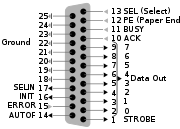
Parallel Port Pinout
|